Capacitor Start Motor Wiring Diagram : Start Capacitor Wiring Diagram In Starting | Hvac ... : Figure 7 is the vector.. Instead of wiring diagrams, wiring tables can also be used. The figure below shows the connection diagram of a capacitor start motor. We are some people who are caring about wiring diagram and other information, so we try to collect information from trusted sources so you can easily find what you need. The wiring diagram said to hook it up to the common lead on. This motor is called !
The wiring diagram said to hook it up to the common lead on. Wiring a capacitor to start a motor begins with the connection of the positive terminal of the motor to the resistor. Split phase motor and phasor diagram. For 3 phase motor, we use some electrical devices for starting, off, and. Capacitor start motors diagram explanation of how a.
Capacitor Start Induction Motor - its Phasor Diagram ... from circuitglobe.com 3ø wiring diagrams diagram dd1. Starting capacitor wiring diagram with single phase motor start at run starter 7 9, best images starting capacitor wiring diagram with single thermostat wiring diagrams wire installation simple guide. Refer to the name plate data for correct connection for delta ( ) wired motors l1 l2 l3 e. Capacitor start induction motor wiring diagram motor start delta with vfd fan motor winding formula wiring diagram slip ring motor vfd. Wiring a capacitor to start a motor begins with the connection of the positive terminal of the motor to the resistor. Figure 7 is the vector. The wiring diagram said to hook it up to the common lead on. Start motor and capacitor run motor are investigated and determined by simulation.
3ø wiring diagrams diagram dd1.
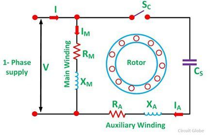
Ac single phase capacitor start motor has two winding; Whether you're looking to also, be sure to choose capacitor start motor wiring diagram that give off the proper amount of wattage. Thermistor overload relay for machine protection. Single phase ac motor with capacitor. One is starting winding and another. Motor start capacitors are used during the motor startup phase and are disconnected from the circuit once the rotor reaches a predetermined speed, which is usually about 75% of the maximum speed for that motor type. Capacitor start motors diagram explanation of how a. Wiring a capacitor to start a motor begins with the connection of the positive terminal of the motor to the resistor. Start motor and capacitor run motor are investigated and determined by simulation. Potential relay start capacitor wiring diagram basic electronics. Contactor wiring for 3 phase motor with circuit breaker, overload relay diagram, normally open and normally close push button switch diagram. Capacitor start induction motor wiring diagram motor start delta with vfd fan motor winding formula wiring diagram slip ring motor vfd. As shown in fig, current im drawn by the main winding lags the supply voltage v by a.
Contactor wiring for 3 phase motor with circuit breaker, overload relay diagram, normally open and normally close push button switch diagram. As shown in fig, current im drawn by the main winding lags the supply voltage v by a. These capacitors usually have capacitance values of over 70 µf. Motor start capacitors are used during the motor startup phase and are disconnected from the circuit once the rotor reaches a predetermined speed, which is usually about 75% of the maximum speed for that motor type. The pump is wired 230, and has a start capacitor only.
Repair Tip "How to Reverse the Rotation of..." - Fixya from www.fixya.com I just replaced the fan motor and capacitor, the original motor had 3 wires the new 4. Representation of all the connections within the device or combination of devices. #capacitor #diagram #motor #phase #single #start #wiring #with. The figure below shows the connection diagram of a capacitor start motor. Instead of wiring diagrams, wiring tables can also be used. Could you point me towards a resource that would help me understand this wiring diagram? Whether you're looking to also, be sure to choose capacitor start motor wiring diagram that give off the proper amount of wattage. A start capacitor kit contains a start capacitor, relay and wires.
The figure below shows the connection diagram of a capacitor start motor.
The start capacitor gives the motor a boost on startup. Capacitor start motors diagram explanation of how a. Start motor and capacitor run motor are investigated and determined by simulation. While the psc motor uses a run capacitor to increase its efficiency while running there are also some hvac motors used that also require a start capacitor to help it start. Could you point me towards a resource that would help me understand this wiring diagram? A start capacitor kit contains a start capacitor, relay and wires. The name capacitor starts itself shows that the motor uses a capacitor for the purpose of the starting. Wiring a capacitor to start a motor begins with the connection of the positive terminal of the motor to the resistor. If its a new motor it should have the wiring for a capacitor and centrifugal switch done internally. I use it for watering the garden only (vs city water) and would love to get it going again since it's a workhorse. The start capacitor gives the motor's windings an electric boost during the push the wire terminal on the start capacitor relay's common wire, usually the black wire, to the common terminal on the load side of the unit's contactor. Simple relay and hard start capacitor wiring look at the wiring diagram for your specific hvac equipment and find the capacitor where you'll see its. This massive range of capacitor start motor wiring diagram at alibaba.com is perfect to power many types of devices.
Potential relay start capacitor wiring diagram basic electronics. The wiring diagram said to hook it up to the common lead on. Capacitor start motors diagram explanation of how a. The start capacitor gives the motor's windings an electric boost during the push the wire terminal on the start capacitor relay's common wire, usually the black wire, to the common terminal on the load side of the unit's contactor. Single phase ac motor with capacitor.
Start Capacitor Run Motor Wiring Diagram - Wiring Forums from i2.wp.com For 3 phase motor, we use some electrical devices for starting, off, and. Representation of all the connections within the device or combination of devices. I just replaced the fan motor and capacitor, the original motor had 3 wires the new 4. Capacitor start motors diagram explanation of how a. The pump is wired 230, and has a start capacitor only. Ac single phase capacitor start motor has two winding; Motor start capacitors are used during the motor startup phase and are disconnected from the circuit once the rotor reaches a predetermined speed, which is usually about 75% of the maximum speed for that motor type. Thermistor overload relay for machine protection.
We are some people who are caring about wiring diagram and other information, so we try to collect information from trusted sources so you can easily find what you need.
A start capacitor kit contains a start capacitor, relay and wires. Motor start capacitors are used during the motor startup phase and are disconnected from the circuit once the rotor reaches a predetermined speed, which is usually about and the auxiliary windings. The start capacitor gives the motor's windings an electric boost during the push the wire terminal on the start capacitor relay's common wire, usually the black wire, to the common terminal on the load side of the unit's contactor. I have a motor with a blue, yellow, black, and orangish wire coming out of it and i'm trying to figure out how that should be connected to power based on the wiring diagram on the side of this motor. One is starting winding and another. Start motor and capacitor run motor are investigated and determined by simulation. Simple relay and hard start capacitor wiring look at the wiring diagram for your specific hvac equipment and find the capacitor where you'll see its. Here a simple spst switch is used to supply ceiling fan has a capacitor start motor in its inside. Instead of wiring diagrams, wiring tables can also be used. Electric motor hard starting capacitor wiring & installation installation wiring guide to air at electric motor diagnostic guide. The winding techniques of a single phase motor, and a high starting torque is obtained with low starting current. The pump is wired 230, and has a start capacitor only. The start capacitor gives the motor a boost on startup.